Tachograph module
The Tachograph module lets you track and analyze driver activity using data from onboard equipment. All information comes directly from the tachograph — it cannot be edited manually. With this module, you can see when drivers are driving, resting, working, or waiting.
Based on these activity records, you can:
-
Understand each driver's workload
-
Verify that drivers follow work and rest regulations
-
Analyze actual work schedules
How to сonfigure data for the module to work
-
Go to the Administrator Panel and open the Vehicles tab.
2. Locate the vehicle linked to the tachograph.
3. Right-click the vehicle and choose Edit.
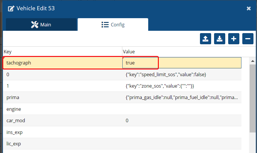
4. In the settings window, go to the Configuration tab.
5. Click the button 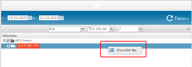 to add the module configuration and select Save.
Setup won’t work unless this configuration is in place.
Required sensors
To display accurate information, the vehicle must have these sensors added:
|
Sensor purpose
|
What it shows
|
Example sensor configuration
|
|
Driver status
|
Tracks the mode switch (driving, rest, work, waiting)
|
 |
|
Card status
|
Shows if the driver’s card is inserted, in use, or not
|
 |
|
Tachograph mode
|
Logs changes in the device’s operating modes
|
 |
How to view tachograph data
1. In your user account, go to the Tachograph section
2. Select the vehicle you want to review
3. Use the calendar to pick a date or time range
4. Click Search
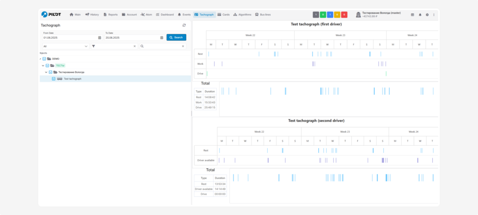
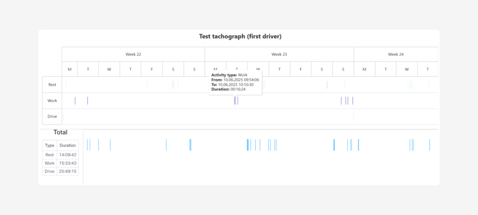
You’ll see a clear, interactive report showing daily and weekly breakdowns of when drivers were driving, resting, waiting, or working.
How the system works behind the scenes
All data comes directly from the tachograph as raw input, which the system automatically processes into clear activity statuses: driving, rest, work, and waiting.
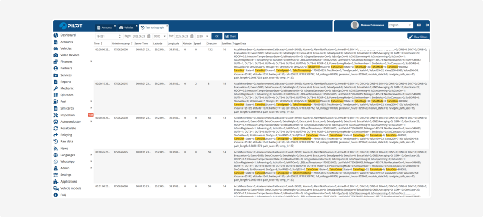
How to interpret tachograph data
Let’s take a closer look at the data tables received directly from the digital tachograph interface — for example, via the CAN bus or another data transmission channel.
These raw data are processed by the monitoring system and help determine:
-
Which driver card was inserted (Table 1)
-
The current status of each driver — whether they are resting, working, or driving — and the card status in each slot (Table 2)
These parameters are encoded as codes and bit values. To interpret them correctly, the data must be processed by the system or analyzed by a specialist during equipment setup.
Below is a decoding of these values according to the tachograph specification.
Table 1
This table describes the structure of the packet that transmits the driver card ID number installed in the tachograph:
0x02 – indicates Driver Card 1 or Driver Card 2.
The specific card is determined by the type of event that generated the data packet.
Event codes associated with these packets help precisely identify which card was inserted and under what condition.
|
№
|
Record field
|
Field size
|
Data format
|
Accepted values
|
|
3
|
Driver card number
|
16
|
U8[16]
|
Identification number of the driver card for the tachograph
|
Table 2
This table describes a data byte from the tachograph interface with the identifier ID: 98.
This byte contains compressed information about the following parameters:
-
Driver activity — such as rest, availability for work, driving, etc.
-
Card slot status — whether a driver card is inserted, and whether it is authorized or not.
The byte is divided into bit fields — a total of 8 bits, split into 4 groups of 2 bits each, where each group represents a specific parameter.
|
Parameter
|
Bits
|
Values
|
|
Driver 1 Activity
|
0..1
|
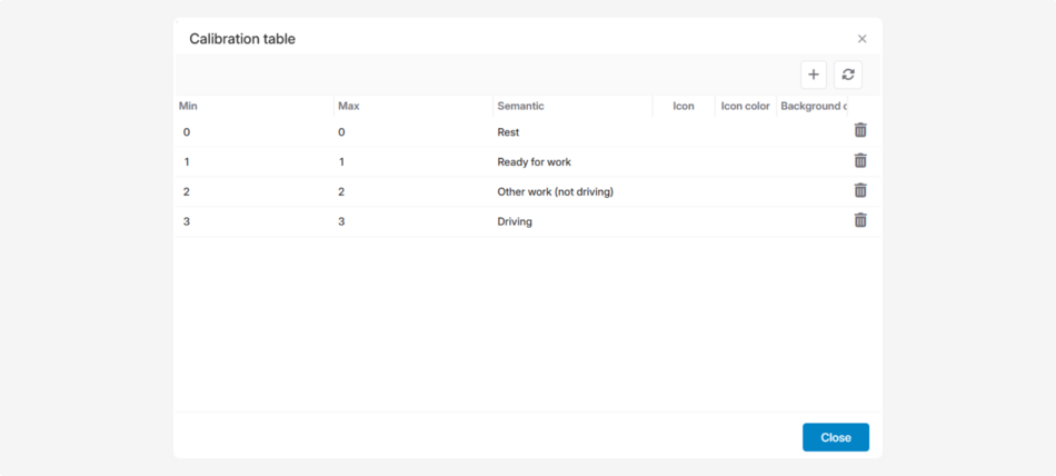
0 – Rest
1 – Availability for work
2 – Work not related to vehicle driving
3 – Driving
|
|
Driver 1 Card slot
|
2..3
|
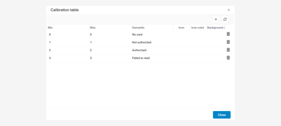
0 – No card
1 – Not authorized
2 – Authorized
3 – Card removal failed
|
|
Driver 2 Activity
|
4..5
|
0 – Rest
1 – Availability for work
2 – Work not related to vehicle driving
3 – Driving
|
|
Driver 2 Card slot
|
6..7
|
0 – No card
1 – Not authorized
2 – Authorized
3 – Card removal failed
|
The information from this byte helps to:
• Connect external equipment to the tachograph
• Obtain accurate data on driver activity
• Configure the system to correctly interpret what the driver is doing
For example: if bits 0–1 = 3, it means Driver 1 is driving the vehicle.
These data are also often used to build calibration tables. Calibration tables are required to convert the raw byte values from the tachograph into readable statuses.
Instead of seeing raw values like 2 or 3, you will see statuses such as "Rest" or "Card authorized."
One byte (8 bits) is divided into four pairs of bits — each pair (2 bits) represents one specific status:
|
Bits (Positions)
|
Parameter
|
Values
|
|
0–1
|
Driver 1 Activity
|
0, 1, 2, 3
|
|
2–3
|
Driver 1 Card slot
|
0, 1, 2, 3
|
|
4–5
|
Driver 2 Activity
|
0, 1, 2, 3
|
|
6–7
|
Driver 2 Card slot
|
0, 1, 2, 3
|
Therefore, you need to configure calibration tables to convert these values into readable driver activity statuses and card states.
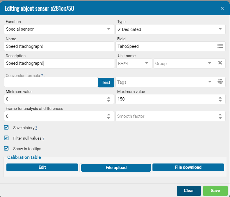
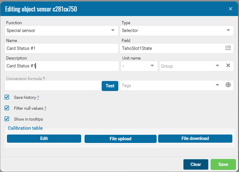
Examples of calibration tables
Calibration Table “Driver Status”. This table is used to decode bit positions 0–1 and 4–5, which represent the activity status of the drivers.
Calibration Table "Card Status". Use this table to interpret the values of bits 2–3 and 6–7, which indicate the status of driver cards.
To learn how to configure a calibration table, click here.
Where to view tachograph reports
The module generates driver activity reports that help you monitor:
— Periods when the driver was behind the wheel
— Time spent resting, waiting, or working
— Driving without a card or with an unauthorized card
— Time intervals for each individual driver